
D.C. Circuit Numericals
1. D.C. Circuit (Numerical) 2. Emf of cell. 3. Heating effect
Section titled “1. D.C. Circuit (Numerical) 2. Emf of cell. 3. Heating effect”Type: 1 (Current, Drift velocity, Resistance and Resistivity)
Formula:
-
Electric current (I) =
-
-
Current density, i.e.
Q. 1. A copper wire has a diameter of 1.02mm and carries a constant current of 1.67A. If the density of free electrons in copper is m-3, calculate the current density and drift velocity of the electrons.
Here,
Diameter,
Current,
Density of free electrons,
(i) Current density,
(ii) Drift velocity,
We have,
(ii)
(i) Current density,
or,
(i) Alternative method
Q. 2.Resistance of a wire of length 1m, diameter 1mm is 2.2 . Calculate its resistivity and conductivity. Ans: m, m-1
Here,
Length, m
Diameter,
Resistance,
- (i) Resistivity,
- (ii) Conductivity, C = ?
We have,
or,
(ii) Conductivity,
Q. 3. A potential difference of 4.5V is applied between the ends of wire that is 2.5m long and has radius of 0.654mm. The resulting current through the wire is 17.6A. What is the resistivity of the wire?
Ans: .
Here,
Potential difference, V = 4.5 V
Length of the wire, l = 2.5m
Radius of the wire,
Current, I = 17.6A
Resistivity,
We have,
Resistance,
or,
or, …(i)
From Ohm’s law,
or,
From eqn (i),
or,
Q. 4. A copper wire has a diameter of 1.02mm, cross-sectional area and resistivity m. It carries a current of 1.67A. Find the electric field magnitude in the wire and the potential difference between two points in the wire 50m apart.
Here,
Diameter of the wire,
Area of cross-section,
Resistivity,
Current, I = 1.67A
(ii) P.d.,
Distance between two points (i.e. length), l = 50m
We have,
(ii) From Ohm’s law,
Since, Resistance,
:
or, P.d,
(i) Electric field,
= 0.035 Vm-1
Q. 5. A tightly coiled spring having 75 coils each 3.50 cm in diameter, is made of insulated metal wire 3.25mm in diameter. An ohm meter connected across its opposite ends reads . What is the resistivity of the metal?
Ans: m
Here,
No. of turns, n = 75
Diameter of coil,
Diameter of the wire,
Resistance,
Resistivity,
We have,
Resistance,
or, here, , C is circumference of coil
Type: 2
Section titled “Type: 2”(Variation of Resistance with Temperature)
Formula:
Section titled “Formula:”Variation of Resistance with Temperature,
, is Temperature coefficient of resistance.
Q. 6. The resistance of a conductor is at C and at C. Calculate its resistance at C.
Section titled “Q. 6. The resistance of a conductor is 10Ω10\Omega10Ω at 50∘50^{\circ}50∘ C and 15Ω15\Omega15Ω at 100∘100^{\circ}100∘ C. Calculate its resistance at 0∘0^{\circ}0∘ C.”Given,
Section titled “Given,”At temperature, C, Resistance,
At temperature, C, Resistance,
At temperature, C, Resistance,
From the variation of resistance with temperature, we have,
For 50°C,
For C,
Dividing (2) by (1)
or,
or,
or,
From (1),
Type: 3
Section titled “Type: 3”(Series and Parallel combination)
Section titled “(Series and Parallel combination)”Formula:
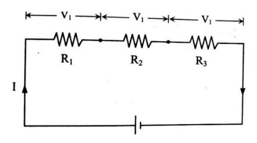
Section titled “Formula:”In Series Combination:
Section titled “In Series Combination:”- (i) Current is same.
- (ii) Voltage drop is different.
- (iii) , ,
- (iv) Total potential (V) =
- (v)
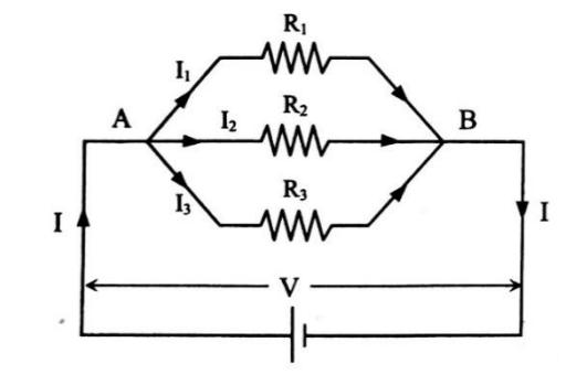
Parallel Combination:
Section titled “Parallel Combination:”- (i) Current is different.
- (ii) Voltage drop is same,
- (iii) ,
- (iv)
- (v)
- (vi) If there are only two resistors in parallel then to find equivalent resistance, we use the formula
Q.7. What is the potential difference across resister in the circuit given below?
Section titled “Q.7. What is the potential difference across 100Ω100\Omega100Ω resister in the circuit given below?”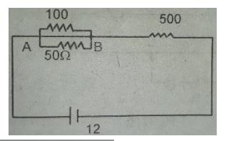
Given,
Emf, E = V = 12V
P.d. across ,
Now,
Then, P.d. across
[V= IR]
= 11.25 V
∴ P.d. across (AB) =
Q.8. Alternative Method
Section titled “Q.8. Alternative Method”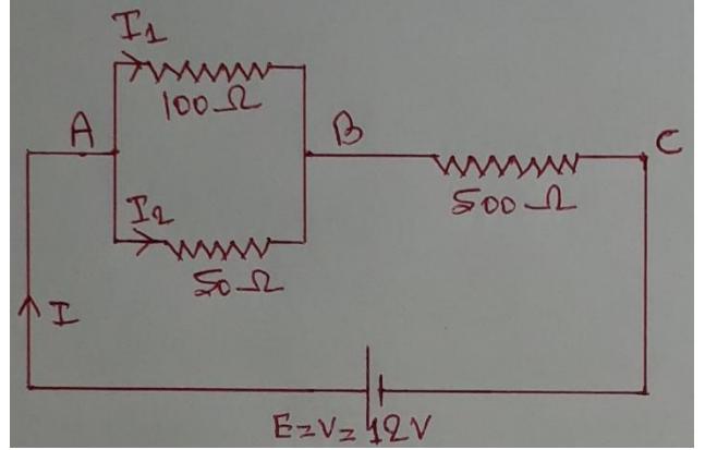
Given,
Emf,
P.d. across ,
Now,
Since, & are in parallel
So, P.d across ,
V = 0.75V
Q.9. Consider the figure below. The current through resister is 4A in the direction shown. What are the currents through the and resistors?
Section titled “Q.9. Consider the figure below. The current through 6Ω6\Omega6Ω resister is 4A in the direction shown. What are the currents through the 25Ω25\Omega25Ω and 20Ω20\Omega20Ω resistors?”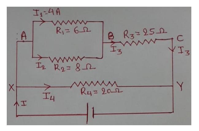
Given,
Current through resistor,
Current through resistor, (I3) =
Current through resistor, (I4) =
Since, are in parallel.
∴ Current through ,
Again arm AC is parallel to arm XY.
Q.10. In the given figure, the current flowing through the resistor is 0.8A. Find the potential drop across resistor.
Section titled “Q.10. In the given figure, the current flowing through the 3Ω3\Omega3Ω resistor is 0.8A. Find the potential drop across 4Ω4\Omega4Ω resistor.”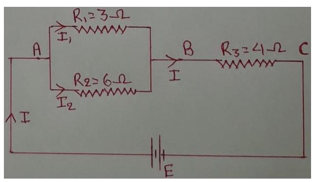
Given, Current through resistor, Potential drop across resistor, Since, are in parallel.
Q. 11. In the given circuit, calculate the potential difference between the points B and D.
Section titled “Q. 11. In the given circuit, calculate the potential difference between the points B and D.”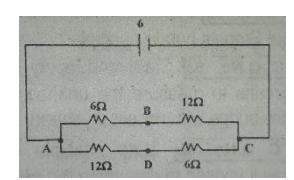
P.d between B & d = ?
Now,
Since,
So the current will be equally divided
P.d across AB =
P.d between B & D = - = 4 -2 = 2V
Emf, Terminal p.d. and internal resistance
Section titled “Emf, Terminal p.d. and internal resistance”Q. 12. A cell of emf 18 V has an internal resistance of 3 . The terminal p.d. of the battery becomes 15 V when connected by a wire. Find the resistance of the wire.
Here,
Emf of cell, E = 18 V
Internal resistance of cell,
Terminal p.d. of the battery, V = 15 V
Resistance of the wire, R = ?
We have circuit formula,
Or,
Or,
Again, using Ohm’s law,
Or,
Or,
Q.13. In the given figure, when switch s is open, the voltmeter v reads 3.08v. When the switch is closed, the voltmeter reading drops to 2.97 V, and the ammeter A reads 1.65A. Find the emf, the internal resistance of the battery and the resistor R. Assume that the two meters are ideal.
Section titled “Q.13. In the given figure, when switch s is open, the voltmeter v reads 3.08v. When the switch is closed, the voltmeter reading drops to 2.97 V, and the ammeter A reads 1.65A. Find the emf, the internal resistance of the battery and the resistor R. Assume that the two meters are ideal.”Here,
The voltmeter reading across the cell in open circuit is emf of cell i.e.
Emf, E = 3.08 V
Also, the voltmeter reading across the cell in closed circuit is terminal p.d. of cell i.e.
Terminal p.d, V = 3.08 V
Current, I = 1.65 A
- (i) E = ?
- (ii) Internal resistance, r = ?
- (iii) Resistance, R = ?
- (i) The voltmeter reading across the cell in open circuit is emf of cell i.e.
Emf,
(ii) Using circuit formula,
Or,
Or,
(iii) Using Ohm’s law,
Or,
Or,
Or,
Q.14. A battery of emf 1.5 V has a terminal p.d. of 1.25 V when a resistor of 25 is joined to it. Calculate the current flowing, the internal resistance and terminal p.d. when a resistance and terminal p.d. when a resistance of 10 replaces 25 resistor.
Section titled “Q.14. A battery of emf 1.5 V has a terminal p.d. of 1.25 V when a resistor of 25 Ω\OmegaΩ is joined to it. Calculate the current flowing, the internal resistance and terminal p.d. when a resistance and terminal p.d. when a resistance of 10 Ω\OmegaΩ replaces 25 Ω\OmegaΩ resistor.”Here,
Emf, E = 1.5 V
Terminal p.d, V = 1.25 V
When 25 resistor is replaced by 25 resistor,
- (i) Current, I’ = ?
- (ii) Internal resistance of cell, r = ?
- (iii) Terminal potential difference, V’ = ?
From fig. (i)
Using circuit formula,
When 25 resistor is replaced by 25 resistor, Fig (ii)
Using circuit formula,
Again,
Q. 15. As shown in the figure, a battery of emf 24 V internal resistance r is connected to a circuit containing two parallel resistors of 3 and 6 in series with an 8 resistor. The current flowing in the 3 is 0.8 A. Calculate the current in the 6 resistor and the internal resistance of the cell.
Section titled “Q. 15. As shown in the figure, a battery of emf 24 V internal resistance r is connected to a circuit containing two parallel resistors of 3 Ω\OmegaΩ and 6 Ω\OmegaΩ in series with an 8 Ω\OmegaΩ resistor. The current flowing in the 3 Ω\OmegaΩ is 0.8 A. Calculate the current in the 6 Ω\OmegaΩ resistor and the internal resistance of the cell.”Ans: 0.4 A and
Here,
Emf of cell, E = 24 V
Current through , A
Current through ,
Internal resistance of cell, r = ?
Since and are in parallel combination
Or,
Or,
Also,
Now, using circuit formula,
Or,
Or,
Or,
Or,
Heating Effect of Current
Section titled “Heating Effect of Current”Electric power consumed (P)
eg. Rating of an electric lamp is 50W - 220V
Q. 16. Two lamps rated 25W - 220V and 100W - 220V are connected to 220V supply. Calculate the powers consumed by the lamps.
Section titled “Q. 16. Two lamps rated 25W - 220V and 100W - 220V are connected to 220V supply. Calculate the powers consumed by the lamps.”Rating of 1st lamp 25W - 220V
and rating of lamp 100W - 220V
Power consumed
For 1st lamp
25W-220V
For 2nd lamp
Req. =
Now,
&
Q. 17. An electric heating element to dissipate 480 watts on 240V mains is to be made from nichrome wire of 1mm diameter. Calculate the length of the wire required if the resistivity of nichrome is ohm-meter.
Section titled “Q. 17. An electric heating element to dissipate 480 watts on 240V mains is to be made from nichrome wire of 1mm diameter. Calculate the length of the wire required if the resistivity of nichrome is 1.1×10−61.1 \times 10^{-6}1.1×10⁻⁶ ohm-meter.”Given,
Power, P = 480 W
Potential, V = 240 V,
Diameter,
Length, l = ?
Resistivity,
We have,
Or, …(1)
But,
Or, .
From (1)
Q. 18. An electric heating element to dissipate 1.2 KW on 240V mains is to be made from Nichrome ribbon 1 mm wide and 0.05 mm thick. Calculate the length of the ribbon required if the resistivity of nichrome is .
Power,
Potential,
Breath,
Thickness,
Length,
Resistivity,
We have,
Or, …(1)
But,
Or,
From (1)
If resistance of voltmeter and resistance of ammeter are neither mentioned nor asked then we consider and .
But either mentioned or asked then we consider them and calculate according to laws of series and parallel combination.
Q. 19. Two resistors of resistance and are joined in series with a 100V supply. A voltmeter of internal resistance is connected to measure the potential difference across resistor. Calculate the reading shown by the voltmeter.
Section titled “Q. 19. Two resistors of resistance 1000Ω1000\Omega1000Ω and 2000Ω2000\Omega2000Ω are joined in series with a 100V supply. A voltmeter of internal resistance 4000Ω4000\Omega4000Ω is connected to measure the potential difference across 1000Ω1000\Omega1000Ω resistor. Calculate the reading shown by the voltmeter.”Ans: 28.57V
Given,
,
Resistance of voltmeter,
Emf, E = 100V
Using circuit formula,
or,
Now P.d. across ,
P.d. across or voltmeter reading

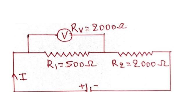
Given.
,
Resistance of voltmeter,
Emf, E = 60V
Case-1: When voltmeter is connected across resistor,
Section titled “Case-1: When voltmeter is connected across 500Ω500\Omega500Ω resistor,”
Using circuit formula,
or,
or,
Now P.d. across ,
∴ P.d. across R1 or voltmeter reading
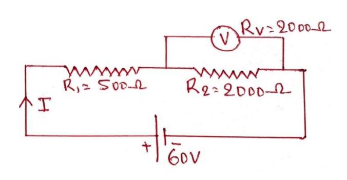
Case-2: When voltmeter is connected across 2000Ω resistor,
Section titled “Case-2: When voltmeter is connected across 2000Ω resistor,”
Using circuit formula,
or,
Now P.d. across ,
∴ P.d. across R1 or voltmeter reading
Q. 21. Two resistance of and are placed in series with 50V mains supply. What will be the reading on a voltmeter of internal resistance 2000 when placed across the 1000 resistor? What fractional change in voltage occurs when voltmeter is connected? Ans: 12V, 25%
Section titled “Q. 21. Two resistance of 1000Ω1000\Omega1000Ω and 2000Ω2000\Omega2000Ω are placed in series with 50V mains supply. What will be the reading on a voltmeter of internal resistance 2000 Ω\OmegaΩ when placed across the 1000 Ω\OmegaΩ resistor? What fractional change in voltage occurs when voltmeter is connected? Ans: 12V, 25%”Given,
,
Resistance of voltmeter,
Emf, E = 50V
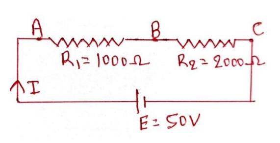
Case-1: When voltmeter is not connected,
Section titled “Case-1: When voltmeter is not connected,”
Using circuit formula,
or,
∴ P.d. across ,
Case-2: When voltmeter is connected across 1000 }\Omega\text{ resistor,} \
Section titled “Case-2: When voltmeter is connected across 1000 }\Omega\text{ resistor,} \”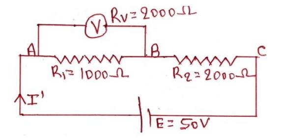
Let I’ be the current flowing in the circuit when voltmeter is connected.
Then using circuit formula,
or,
Now P.d. across R2, V2 = I’ R2 = × 2000 = 37.5 V
P.d. across ,
So fractional change in voltage = (in magnitude)
And % change in voltage =
Q. 88 Twelve cells each of emf 2 V and of internal resistance 0.5 ohm are arranged in a battery of n rows and external resistance 0.4 ohm is connected to the poles of the battery. Estimate the current flowing to the resistance in terms of n.
Section titled “Q. 88 Twelve cells each of emf 2 V and of internal resistance 0.5 ohm are arranged in a battery of n rows and external resistance 0.4 ohm is connected to the poles of the battery. Estimate the current flowing to the resistance in terms of n.”Q.73. An electric lamp consumes 60 W at 220 V. How many dry cells of emf 1.5 V and internal resistance of are required to glow the lamp?
Section titled “Q.73. An electric lamp consumes 60 W at 220 V. How many dry cells of emf 1.5 V and internal resistance of 1Ω1\Omega1Ω are required to glow the lamp?”Here,
Power, P = 60 W
Type: 5
Section titled “Type: 5”(Conversion of galvanometer into Ammeter & Voltmeter)
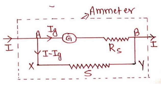
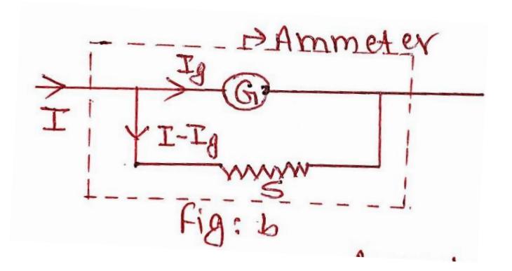
# Conversion of galvanometer into an ammeter:
Section titled “# Conversion of galvanometer into an ammeter:”Since, galvanometer and shunt are in parallel combination, ∴ p.d. across shunt (S) = p.d. across galvanometer (G)
or,
or,
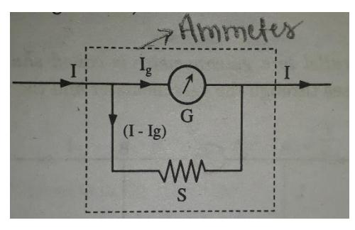
Fig: Conversion of galvanometer into an ammeter
# Conversion of galvanometer into voltmeter:
Section titled “# Conversion of galvanometer into voltmeter:”Maximum voltage that can be measured by voltmeter,
or, or,
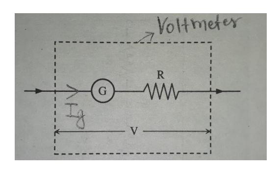
Fig: Conversion of galvanometer into voltmeter
Q. 67. The resistance of the coil of galvanometer is and a current of 0.0224 A causes it to deflect full scale. The only shunt available has a resistance . What resistance must be connected in series with the coil to make it an ammeter of range 0 - 20 A?
Section titled “Q. 67. The resistance of the coil of galvanometer is 9.36Ω9.36\Omega9.36Ω and a current of 0.0224 A causes it to deflect full scale. The only shunt available has a resistance 0.025Ω0.025\Omega0.025Ω . What resistance must be connected in series with the coil to make it an ammeter of range 0 - 20 A?”Ans: 12.94 Ω
Given,
Section titled “Given,”Resistance of galvanometer,
Current through the galvanometer for full scale deflection, A
Shunt,
current through ammeter, I = 20A
Since arm AB is parallel to arm XY
Q.67 & 75 are same.
Q. 81. A voltmeter coil has resistance and a resistor of 1.15 K is connected in series. It can read potential differences upto 12 volts. If the same coil is used to construct an ammeter which can measure currents upto 2A, what should be the resistance of the shunt used?
Section titled “Q. 81. A voltmeter coil has resistance 50Ω50 \Omega50Ω and a resistor of 1.15 K Ω\OmegaΩ is connected in series. It can read potential differences upto 12 volts. If the same coil is used to construct an ammeter which can measure currents upto 2A, what should be the resistance of the shunt used?”Given,
Resistance of galvanometer,
Section titled “Resistance of galvanometer, G=50ΩG = 50\OmegaG=50Ω”Series resistance,
Maximum voltage that can be measured by voltmeter, V = 12 V
Maximum current through ammeter, I = 2 A,
Shunt, S = ?
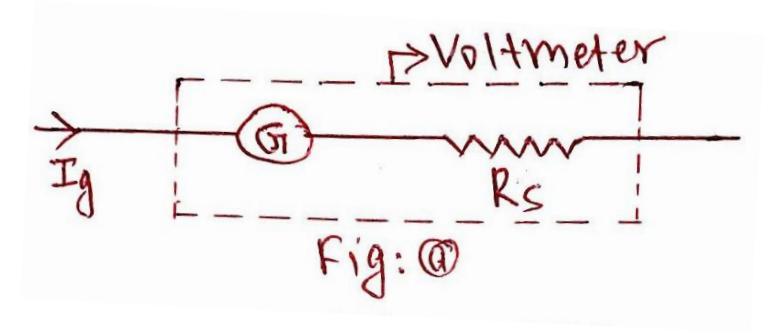
Case:1
Section titled “Case:1”From fig (a)
Maximum voltage that can be measured by voltmeter
From Fig (b), Since galvanometer and Shunt are in parallel,
P.d. across G = P.d. across S
Ans:
A potential divider is an arrangement of resistors in series across a given p.d. to provide a known fraction of the potential difference. Fig.//// shows a potential divider with resistances and across a p.d. of V. The current flowing, I in the circuit is given by
Then p.d. across ,
The fraction of V obtained across is .
A resistor with a sliding contact can be used as a potential divider. This arrangements provides a continuously variable p.d. from zero to the full supply value.