
D.C. Circuit Notes
# Current Electricity:
Section titled “# Current Electricity:”The branch of physics which deals with the study of motion of charge through a conductor, Semi-conductor or electrolyte is known as current electricity.
Electric Current (I):
Section titled “Electric Current (I):”It is defined as the flow of charge per unit time. It is denoted by ‘I’. It is scalar quantity.
Mathematically,
Electric current (I) = ----- (1)
Its unit is CS-1 or Ampere (A)
From quantization of charge, q = ne, then equation (1) becomes
For I = 1A & t = 1 sec, we have
Or,
n = 6.25×10¹⁸
Thus, current is said to be of one ampere if number of electrons flow through a conductor in 1 second.
Current carriers in different materials:
Section titled “Current carriers in different materials:”Conductor: Free electrons
Electrolyte: +ve charge (cation) and -ve charge (anion)
Gases: +ve charge and free electrons Semi-conductor: Free electrons and holes
# Direction of current
Section titled “# Direction of current”# Conventional flow of current:
Section titled “# Conventional flow of current:”The flow of current from positive terminal to negative terminal of a battery in a circuit is known as conventional flow.
# Electron flow:
Section titled “# Electron flow:”The actual flow of current in conductor is due to the flow of electrons which from negative terminal to positive terminal of a battery in a circuit is known as electron flow (directional flow).
Types of current
Section titled “Types of current”i. Direct current (D.C.)
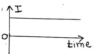
Section titled “i. Direct current (D.C.)”Current is said to be direct current if its magnitude and direction do not change with respect to time.
ii. Alternating current (A.C.)
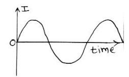
Section titled “ii. Alternating current (A.C.)”Current is said to be alternating current if magnitude of current changes with the time and direction reverses periodically.
# Conductor:
Section titled “# Conductor:”Those substances which have a large number of free electrons even at normal temperature are known as conductors. For examples: copper, iron, brass etc.
# Insulators:
Section titled “# Insulators:”Those substances which do not have any free electron at normal temperature are known as insulators. For examples: wood, paper, plastic etc.
# Semiconductor:
Section titled “# Semiconductor:”Those substances whose conductivity lies between conductors and insulators are known as semiconductor. For example Silicon, Germanium etc.
# Mechanism of metallic conduction:
Section titled “# Mechanism of metallic conduction:”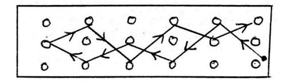
Since conductor contains a large number of free electrons even at normal temperature. The free electrons are moving with very high velocity in random direction due to which the average velocity is zero. So, there is no electric current although the electrons are moving with high velocity without application of electric field.
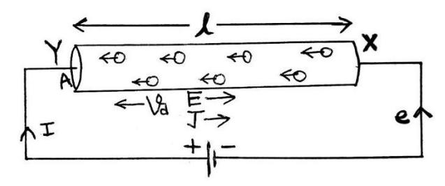
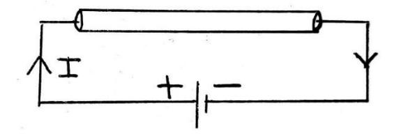
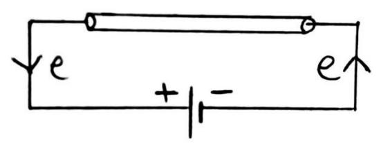
Fig: Electrons passing through the conductor in an applied electric field.
Let us consider a conductor XY of length ‘l’ and area of cross section ‘A’. Let ‘n’ be the number of free electrons per unit volume and ‘e’ be the charge on each electron. The conductor XY is connected with source (battery) in such a way that the end X is connected with negative terminal and Y is connected with positive terminal. When the conductor is connected with the source, the free electrons experience columbic repulsive force and they get accelerated. When free electrons get accelerated, a collision takes place between them and loses their velocity. By this process, the free electrons attain certain average velocity on moving from X to Y. The average velocity gained by electrons in specific direction on the application of electric field is known as drift velocity.
Now, let us consider ‘n’ be the number of free electrons per unit volume i.e.
Volume of conductor, V = AlIn volume V, total number of free electrons (N) = nV = n A l
Total charge (q) = Ne
Or,
Since electric current is defined as the flow of charge per unit time.
∴ Electric current (I) =
Or, I = n A Vd e (∵ Drift velocity, Vd = )
∴ I = Vd e n A (or simply I = v e n A)
This is the required relation between current and drift velocity of electrons.
# Current density (J):
Section titled “# Current density (J):”The current density at any point in the conductor is defined as the current flowing per unit cross-sectional area perpendicular to the direction of the flow. It is denoted by J. It is a vector quantity.
From the expression of drift velocity,
Or,
Since, current density,
∴ This is the required expression for current density.
# Ohm’s law: (i.e. V=IR)
Section titled “# Ohm’s law: (i.e. V=IR)”Ohm’s law states that,” the current following through a conductor is directly proportional to potential difference across its two ends.” Keeping physical conditions (temperature and mechanical strain) constant.
Let ‘V’ the potential difference between two ends of a conductor and current flowing through it is ‘I’. Then, according to Ohm’s law, we can write
\ni.e.
Where R is proportionality constant and known as resistance of conductor. Its unit is or ohm .
# Experimental verification of Ohm’s Law:
Section titled “# Experimental verification of Ohm’s Law:”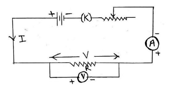
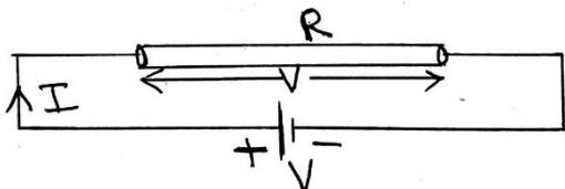
Fig: Experimental Verification of Ohm’s law
The experimental setup for verification of Ohm’s law is shown in figure above. In the figure, a resistor of resistance ‘R’ is connected with a battery through ammeter (A), variable resistance ( ) and a key (K) as shown in a figure. A voltmeter (V) is connected across the resistor (i.e. in parallel with resistor). When circuit is open, no current flows through it and the ammeter and voltmeter do not show any reading. When circuit is closed, an amount of current flows through the circuit measured by ammeter and corresponding potential is measured by voltmeter. Now, the value of current in the circuit is changed with the help of variable resistance (rheostat, ). Let be the
current flowing through the circuit and corresponding potential is . Let , , … be the current flowing through the circuit for different value of and corresponding potential are respectively. Experimentally, it has been found that
This shows = constant
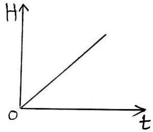
If a graph is plotted between current and voltage, straight line passing through the origin is obtained.
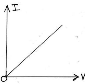
The above experiment shows that current flowing through a conductor is directly proportional to potential difference across its two ends, which is Ohm’s law.
# Ohmic conductor:
Section titled “# Ohmic conductor:”A conductor which obeys Ohm’s law is called ohmic conductor. For example: metals (copper, silver, iron etc)
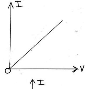
When a graph is plotted between current and voltage, a straight line passing through the origin will be obtained. I-V graph of an ohmic conductor is shown in figure.
# Non-ohmic conductor:
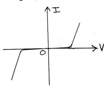
Section titled “# Non-ohmic conductor:”A conductor which does not obey Ohm’s law is known as nonohmic conductor. For example: electrolyte, junction diode etc. If a graph is plotted between current and voltage for non ohmic conductor, a straight line passing through origin will not be obtained.
I-V graph of a diode (a non- ohmic conductor) is shown in figure.
# Resistance:
Section titled “# Resistance:”The property of conductor by virtue of which it opposes the flow of current through it is known as resistance. And the devise is called resistor. It is denoted by R and unit is Ohm .
# Law of resistance:
Section titled “# Law of resistance:”Let us consider a conductor of length (l) and area of cross section (A). Let R be the resistance of the conductor. Experimentally it is found that resistance of conductor is
(i) directly proportional to length of conductor
i. e. …(i)
(ii) inversely proportional to area of cross section of the conductor.
i.e. …(ii)
On combining (i) and (ii)
Or,
where ’ ’ is proportionality constant called resistivity of a conductor.
Or,
If and l = 1 m, then
Thus, resistivity of a conductor is defined as the resistance of conductor of unit area of cross sectional area per unit length. It’s unit is .
Its dimensional Formula is [ML3T-3A-2]
It is the properties of a Material. So, independent to the dimension of conductor.
# Conductivity:
Section titled “# Conductivity:”It is defined as the reciprocal of resistivity. It is denoted by . Mathematically,
Conductivity, Or,
Its unit is m-1
# Conductance:
Section titled “# Conductance:”It is defined as the reciprocal of resistance.
It is denoted by ‘C’
Mathematically,
Conductance,
Its unit is or ohm-1 or (mho) or Sieman (S).
# Variation of resistance with temperature:
Section titled “# Variation of resistance with temperature:”Let us consider a conductor of resistance at C and at C.
Experimentally, it has been found that the increase in resistance is
(i) directly proportional to original resistance i.e. Resistance at 0°C
i.e. …(i)
(ii) directly proportional to increase in temperature
i.e. …(ii)
Combining (i) and (ii) we get,
Or,
where ’ ’ is proportionality constant and known as temperature coefficient of resistance.
Or,
Thus, Temperature Coefficient of resistance of a conductor is defined as the increase in resistance per unit original resistance i.e. resistance at 0°C per degree rise in temperature. Its unit is °C-1 or K-1.
The value of temperature Coefficient is positive for conductor (metals), negative for semi-conductors and almost zero for standard resistor (constantan and manganin).
Also, from equation (a)
This is the required expression for variation of resistance with temperature.
#Grouping of resistance:
Section titled “#Grouping of resistance:”Resistors are to be grouped in circuit to decrease or increase the equivalent resistance of the circuit.
(i) Series Combination:
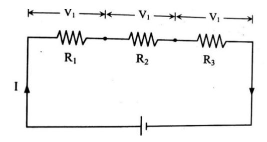
Section titled “(i) Series Combination:”The combination in which one end of resistance is connected to the one end of another resistance and so on, so that same current flows through all the resistors then this type of combination is called series combination of resistances.
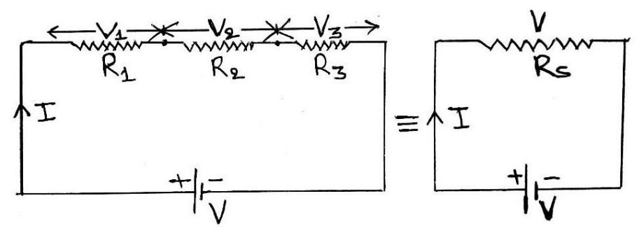
Fig: Series Combination of resistors
Fig: Series equivalent resistance
Let us consider three resistors of resistance , and are connected in series with a battery of potential V. Let ‘I’ be the current supplied by the battery. Since resistors are in series combination, so same current ‘I’ flows through each resistor but potential difference is different depending upon resistance of resistor. Let , and be the potential across , and respectively. Let equivalent resistance of the circuit is ’ ’.
Then
Now,
Total potential,
Or,
Or, …(i)
If Rs is the equivalent resistance of the circuit, then we can write
…(ii)
From (i) and (ii),
This is the required expression for equivalent resistance in series combination.
Properties of series combination:
Section titled “Properties of series combination:”- (i) Same amount of current flows through all resistors.
- (ii) The Potential is divided and potential difference is different depending upon resistance of resistor.
- (iii) The value of equivalent resistance is equal to the sum of individual resistance.
- (iv) The value of equivalent resistance is greater than that of even the greatest resistance.
(ii) Parallel Combination:
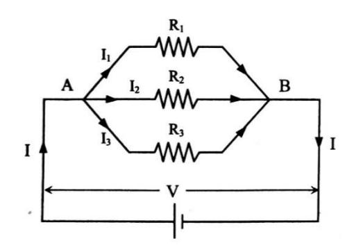
Section titled “(ii) Parallel Combination:”The combination in which one end of all resistors are connected with positive terminal and another end of all resistors is connected with negative terminal of a battery so that voltage drop across each resistance remains same is known as parallel combination of resistors.
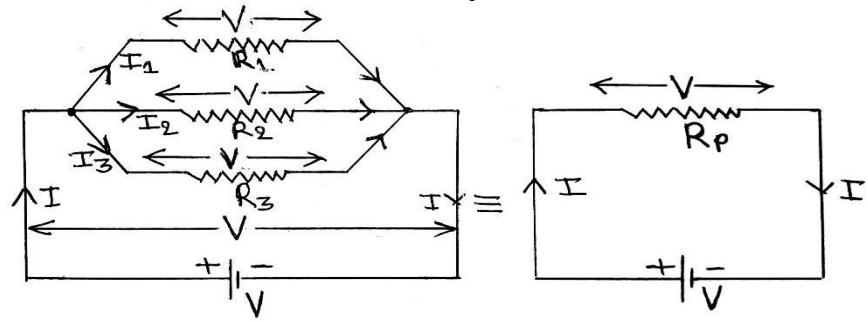
Fig: Parallel Combination of resistors
Fig: Parallel equivalent resistance
Let us consider three resistors of resistance , and are connected in parallel combination with a battery of potential ‘V’. Since resistors are in parallel combination, so potential difference across each resistor is same (i.e. V). Let I be the total current supplied by the battery. From point A, the current is divided into , and and flows through , and respectively. Let be the equivalent resistance of circuit.
Then, Current through ,
Current through ,
Current through ,
Now,
The equivalent resistance of the circuit is Rp. Then, we can write,
From (i) and (ii)
Properties of parallel combination:
Section titled “Properties of parallel combination:”- (i) The potential difference is same across each resistor.
- (ii) The current is divided and the value of current different depending upon resistance of resistor.
- (iii) The reciprocal of equivalent resistance is equal to the sum of the reciprocal of individual resistance.
(iv) The value equivalent resistance is less than that of even the smallest resistance.
Note: If there are only two resistors in parallel then to find equivalent resistance, it is better to use the formula
or instead of
1. D.C. (Numerical) 2. Heating effect 3. Emf, cell
Section titled “1. D.C. (Numerical) 2. Heating effect 3. Emf, cell”Type: 1 (Current, Drift velocity, Resistance
and Resistivity)
Formula:
-
- Electric current (I) =
-
-
- Current density, i.e.
-
- V = IR
- Q. 1. A copper wire has a diameter of 1.02mm and carries a constant current of 1.67A. If the density of free electrons in copper is , calculate the current density and drift velocity of the electrons.
Ans: 1.5×10⁻⁴ms-1, 2.04×10⁶ Am-2
- Q. 2.Resistance of a wire of length 1m, diameter 1mm is 2.2 . Calculate its resistivity and conductivity. Ans: m, m-1
- Q. 3. A potential difference of 4.5V is applied between the ends of wire that is 2.5m long and has radius of 0.654mm. The resulting current through the wire is 17.6A. What is the resistivity of the wire?
Ans: .
Q. 74. A copper wire has a diameter of 1.02mm, cross-sectional area and resistivity
Ans: , 1.75V
Q. 80. A tightly coiled spring having 75 coils each 3.50 cm in diameter, is made of insulated metal wire 3.25mm in diameter. An ohm meter connected across its opposite ends reads 1.74 . What is the resistivity of the metal?
Ans: m
Type: 2
Section titled “Type: 2”Variation of Resistance with Temperature, , is Temperature coefficient of resistance.
Q. 83. The resistance of a conductor is at C and at C. Calculate its resistance at C. Ana:
Type: 3
Section titled “Type: 3”(Series and Parallel combination)
Section titled “(Series and Parallel combination)”Formula:
Section titled “Formula:”In Series Combination:
Section titled “In Series Combination:”- (i) Current is same.
- (ii) Voltage drop is different.
- (iii) , ,
- (iv) Total potential (V) =
- (v)
Parallel Combination:
Section titled “Parallel Combination:”- (i) Current is different.
- (ii) Voltage drop is same,
- (iii) ,
- (iv)
(v)
(vi) If there are only two resistors in parallel then to find equivalent resistance, we use the formula
or instead of
Electromotive force, terminal potential difference and internal resistance of a cell
Section titled “Electromotive force, terminal potential difference and internal resistance of a cell”Electromotive force (Emf):
Section titled “Electromotive force (Emf):”The property of a cell by virtue of which the charge moves in the circuit in a particular direction is known as electromotive force (e.m.f). The electromotive force is not a force but just the historical name. The Emf of a cell can be defined as the work done by the cell to move unit positive charge (+1C) throughout the complete electrical loop. It can also be defined as the potential difference between the two terminals of the cell in open circuit (i.e. when no current flows). It is denoted by ‘E’. Its unit is volt. Mathematically,
Emf,
Terminal potential difference:
Section titled “Terminal potential difference:”Terminal potential difference of a cell is defined as the amount of work done by the cell to move a unit positive charge (+1C) through external/load resistance. It can also be defined as the potential difference between the two terminals of the cell in closed circuit (i.e. when current flows). It is denoted by ‘V’. Its unit is volt.
Mathematically,
Terminal potential difference,
Internal resistance:
Section titled “Internal resistance:”The resistance offered by electrolyte between the electrodes of a cell is known as internal resistance. It is denoted by ‘r’. Its unit is Ohm .
Factors on which the internal resistance of a cell depends are
Factors on which the internal resistance of a cell depends are
(i) Nature of electrolyte:
Internal resistance, r is inversely proportional to conductivity ( )
- (ii) Distance between the electrodes: “internal resistance, r” is directly proportional to distance
- (iii) Area of electrodes:
Internal resistance, r is inversely proportional to area of electrodes (A)
(iv) Concentration:
Internal resistance, r is inversely proportional to concentration of electrolyte
(v) Temperature:
Internal resistance, r is inversely proportional to temperature of electrolyte.
# Relation between emf (E), terminal p.d. (V) and internal resistance (r):
Section titled “# Relation between emf (E), terminal p.d. (V) and internal resistance (r):”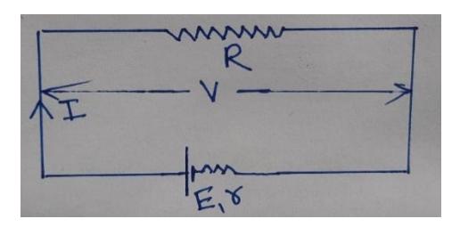
Fig: Ckt. of emf, terminal p.d. and internal resistance
Let us consider a cell of e.m.f. (E) and internal resistance (r) is connected with external resistance R. Let I be the current flowing through the circuit and terminal potential difference is V. Since internal resistance always in series combination with external resistance, so total resistance of circuit becomes R+ r.
Current,
or,
or,
or,
or, (where )
which is the relation between e.m.f., terminal p.d and internal resistance for discharging circuit. In case of of charging circuit, current flows in reverse direction. So, the above relation becomes E = V-Ir
Heating effect of current
Section titled “Heating effect of current”Heating effect of current:
Section titled “Heating effect of current:”When current flows through a conductor, heat develops in it. This effect of current is known as heating effect of current.
When current flows through a conductor, the free electrons of the conductor come in motion and collision takes place between them. Due to the collision moving electrons lose their kinetic energy and some part of their kinetic energy is converted into heat energy.
Joule’s law of heating:
Section titled “Joule’s law of heating:”Let us consider a conductor of resistance R. Let an amount of current I is passed through the conductor for time ‘t’. According to Joule’s law of heating, the heat developed in the conductor is
(i) directly proportional to square of magnitude of current flowing through the conductor.
i.e. …(i)
(ii) directly proportional to resistance of conductor.
(iii) directly proportional to the time for which current is passed through the conductor.
On combining (i), (ii) and (iii) we get,
or,
Where ‘k’ is proportionality constant and its value is 1 in S.I.
The above result also can be written as
where ‘J’ is Joule’s equivalent and its value is 4.2 joules/calorie.
Derivation for the expression of heat developed in a wire
Section titled “Derivation for the expression of heat developed in a wire”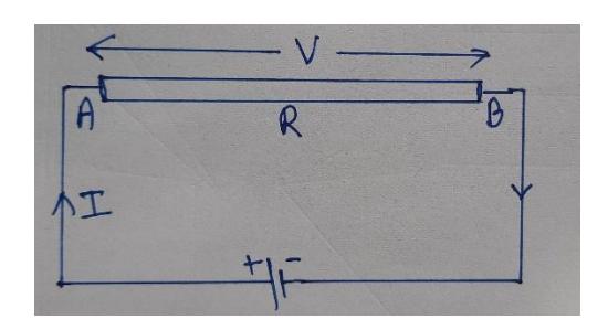
Let us consider a wire AB of resistance R in a circuit as shown in Fig. Let I be the steady current passing through it.
In time ‘t’ the total charge ‘q’ passing through B to A is given by
or,
Let the potential difference between A and B be V. Then,
The work done to transfer the charge q from B to A is given by
From Eqs. (i), (ii) and (iii) we get
Or,
It the wire is a passive resistor, all the electrical energy is converted into the heat energy, H.
So, W = H and we have,
Joule
This is the expression for heat developed in a wire of resistance R.
# Experimental verification of Joule’s law of heating:
Section titled “# Experimental verification of Joule’s law of heating:”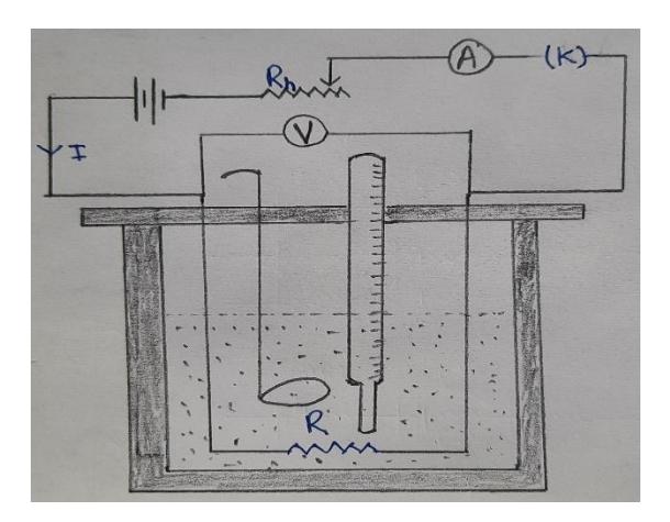
Fig: Experimental setup of Joule’s law of heating
The experimental setup for verification of Joule’s law of heating is shown in figure above. It consists of a calorimeter with stirrer filled with water about two third of its volume. A heating coil is placed well inside water. The heating coil is connected with a battery through a key, a rheostat (variable resistance) and an ammeter as shown in figure. The variable resistance is used to change the value of current and ammeter is used to measure the value of current.
(i) Verification of first law (i.e. )
Section titled “(i) Verification of first law (i.e. H∝I2H \propto I^2H∝I2 )”Let ‘m’ be the mass of water in the calorimeter of water equivalent ‘W’, specific heat capacity of water is ‘S’.
Now, amount of current is passed through the heating coil of resistance R for time ‘t’. It is found that the temperature of water and calorimeter increases from to . Now heat developed is
Let H2, H3 and H4 be the heat developed when different amounts of current I2, I3,I4…are passed through the same heating coil for some time, it is found that
Now we can write
= constant
It gives
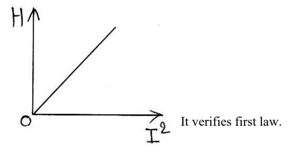
If we plot a graph for different value of H and I2, a straight line passing through the origin will be obtained.
(ii) Verification of second law (i.e. H∞ t)
Section titled “(ii) Verification of second law (i.e. H∞ t)”To verify this law, heating coils of different lengths are taken. Let , , , …be the resistances of different heating coils. If same amount of current is passed through the different heating coils of resistance , , , for same time the corresponding heat developed is found to be , , , …respectively. Now, it is found that
Now we can write
= constant
It gives
If we plot a graph for different value of H and R, a straight line passing through the origin will be obtained.
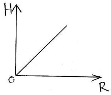
It verifies second law.
(iii) Verification of third law (i.e. )
Section titled “(iii) Verification of third law (i.e. H∝tH \propto tH∝t )”To verify this law, same amount of current is passed through the same heating coil for different time , , , …the corresponding heat developed are , , , …respectively. It is found that
Now we can write
It gives H ∝ t
If we plot a graph for different value of H and t, a straight line passing through the origin will be obtained.
It verifies third law.
# Electric power:
Section titled “# Electric power:”This is defined as the electrical energy per unit time.
Mathematically,
Electric power,
…(i)
…(ii) Since,
Since,
…(iii)
From (i), (ii) and (iii)
(iii)
# One unit or 1 kilowatt-hour of electrical energy:
Section titled “# One unit or 1 kilowatt-hour of electrical energy:”From the definition of electric power,
Electric power,
Electric energy =
If P=1 kw and t=1 hour then
Electric energy =
=1 kwhr
= 1 unit
Electric energy consumed is said to be one unit if an electric device of 1kw power is used for 1 hour.
Numerical Questions:
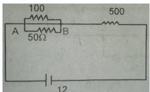
Section titled “Numerical Questions:”Q.87. What is the potential difference across resister in the circuit given below?
Ans: V
Alternative Method
Section titled “Alternative Method”Q.76. Consider the figure below. The current through resister is 4A in the direction shown. What are the currents through the and resistors?
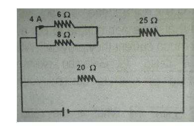
Ans: 7A & 9.95A
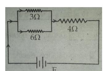
Section titled “Ans: 7A & 9.95A”Q.77. In the given figure, the current flowing through the resistor is 0.8A. Find the potential drop across resistor.
Ans: 4.8 V
Heating Effect of Current
Section titled “Heating Effect of Current”Electric power consumed (P)
since :
eg. Rating of an electric lamp is 50W - 220V
Q. 68. Two lamps rated 25W - 220V and 100W - 220V are connected to 220V supply. Calculate the powers consumed by the lamps.
Ans 16 W & 4 W.
Q. 84. An electric heating element to dissipate 480 watts on 240V mains is to be made from nichrome wire of 1mm diameter. Calculate the length of the wire required if the resistivity of nichrome is ohm-meter.
Ans: 85.68 m.
Q. 86. An electric heating element to dissipate 1.2 KW on 240V mains is to be made from Nichrome ribbon 1 mm wide and 0.05 mm thick. Calculate the length of the ribbon required if the resistivity of nichrome is .
Ans: 2.182 m
Q. 78. A cell of emf 18 V has an internal resistance of 3 . The terminal p.d. of the battery becomes 15 V when connected by a wire. Find the resistance of the wire.
Ans: 15 Ω
# Galvanometer:
Section titled “# Galvanometer:”It is an electrical instrument which is used to detect the flow of current in the circuit. It also gives the direction of current and measures small amount of current and potential difference. The resistance of galvanometer is low. Its symbol is
(G)
# Ammeter:
Section titled “# Ammeter:”An ammeter is an electrical instrument used to measure the current passing through it. The resistance of ammeter is very low. It is always connected in the series in the circuit. Its symbol is
# Voltmeter:
Section titled “# Voltmeter:”Voltmeter is an electrical instrument used to measure the potential difference across it. The resistance of voltmeter is very high. It is always connected in the parallel with the load resistance in the circuit. Its symbol is
# Shunt:
Section titled “# Shunt:”It is a low value resistance which is connected in parallel with galvanometer to convert the galvanometer into an ammeter.
# Conversion of galvanometer into an ammeter:
Section titled “# Conversion of galvanometer into an ammeter:”Galvanometer is an electrical instrument which is used to detect the flow of current in the circuit. The resistance of galvanometer is low.
Ammeter is an instrument used to measure the current passing through it. The resistance of ammeter is very low. It is always connected in the series in the circuit.
Galvanometer is converted into ammeter by using suitable shunt (a low value resistance) in parallel with it.
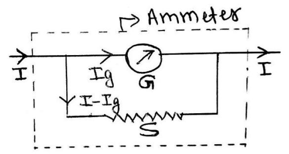
Fig: Conversion of galvanometer into an ammeter
Let us consider a galvanometer of resistance ‘G’ and shows full scale deflection when an amount of current flows through it. We have to convert the galvanometer into an ammeter which can measure current upto ‘I’ ampere. For this, let us connect a shunt ‘S’ (a low value resistance) in parallel with the galvanometer.
The value of shunt is chosen in such a way that only desirable amount of current flows through the galvanometer and remaining current flows through the shunt.
Since, shunt and galvanometer are in parallel combination,
∴ p.d. across shunt (S) = p.d. across galvanometer (G)
Or,
Or,
This is the required value of shunt to convert a galvanometer into an ammeter to measure current upto I ampere.
Now the resistance of ammeter is the equivalent resistance of parallel combination of shunt and galvanometer So,
So, the resistance of ammeter (RA) is very small (even smaller than G & S). This is the necessary criterion to be an ammeter.
# Conversion of galvanometer into voltmeter:
Section titled “# Conversion of galvanometer into voltmeter:”Galvanometer is an electrical instrument which is used to detect the flow of current in the circuit. The resistance of galvanometer is low.
Voltmeter is an instrument used to measure the potential difference across it. The resistance of voltmeter is very high. It is always connected in the parallel with the load resistance in the circuit.
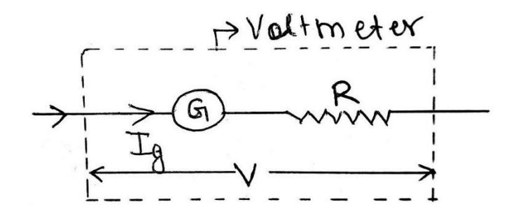
Fig: Conversion of galvanometer into voltmeter
Section titled “Fig: Conversion of galvanometer into voltmeter”Let us consider a galvanometer of resistance ‘G’ and shows full scale deflection when an amount of current flows through it. We have to convert the galvanometer into voltmeter measure to measure potential difference upto V volt. For this, let us connect a high value resistance ‘R’ in series with galvanometer. Since galvanometer and high value resistance(R) are in series combination, so total resistance becomes R+G Now,
Where R is required value of high value resistance to convert a galvanometer into voltmeter to measure potential difference upto V volt.
The resistance of voltmeter .
As the value of R is high, so is also high. This is the necessary criterion to be a voltmeter.