
Capacitor Notes
Capacitor
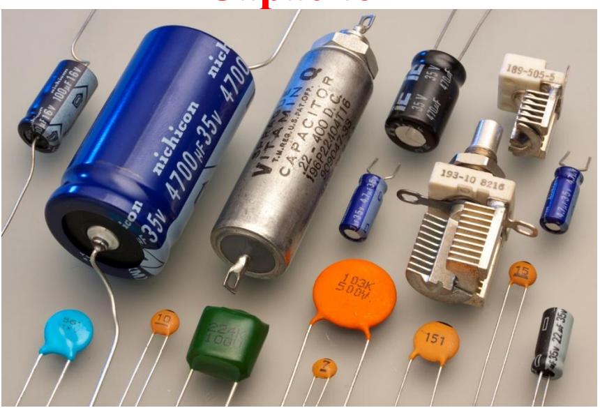
Section titled “Capacitor”Capacitor is a device/conductor which is used to store the electrical energy in the form of charge. It is used in some electrical devices that requires very high current (25A - 50A) to start them due to static friction (like fan, motor, computer, camera flash). Capacitor stores the electrical energy in the form of charge and supply at once to such electrical in the form of large current. Battery/ cell also converts chemical energy to electrical energy in the form of current but that current is small.
Capacitance of a capacitor:
Section titled “Capacitance of a capacitor:”The capacity or ability of capacitor to store electrical energy in the form of charge is known as capacitance of capacitor. If Q be the charge given to a capacitor so that its potential increases to V then experimentally, it is found that the charge stored in the capacitor is directly proportional to the electrical potential (p.d). i.e.
Or, Q = CV where C is proportionality constant and known as capacitance of a capacitor.
Or,
In other words, capacitance of a capacitor can also be defined as the ratio of charge to potential difference. Its unit is coulomb per volt which also known as Farad (F).
If p.d. V = 1 V and Q = 1 C then C = 1 Farad
Thus, capacitance of a capacitor is said to be of 1 Farad if 1Coulomb charge can raise its potential through 1 Volt. Capacitance of 1 Farad is extremely high value so generally capacitance is measures in F.
1 micro-micro Farad ( F) = 1 pico-farad (pF) = 1×10-12 F
Note: Although , the capacitance of a capacitor does not depend upon charge and potential but depends upon nature of material and dimensions of capacitor.
Types of capacitor:
Section titled “Types of capacitor:”There different types of capacitor;
- (i) Isolated sphere as capacitor, (ii) Spherical capacitor (Two concentric spherical shell)
- (iii) Parallel plate capacitor
(i) Isolated sphere as capacitor:
Section titled “(i) Isolated sphere as capacitor:”Let us consider an isolated spherical conductor of radius ‘R’ and charge on its surface is ‘Q’.
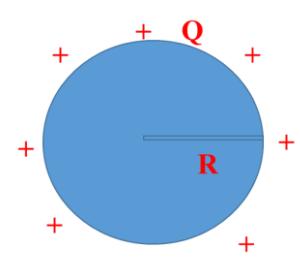
The potential at any point on the surface is given by
,
According to the definition of capacitance, (capacitance), so we can write
Capacitance of an isolated sphere,
Thus capacitance of isolated sphere depends upon
- Radius as (i)
- Permittivity of medium as (ii)
In CGS- system,
So in CGS-system, capacitance of an isolated charged sphere is numerically equal to its radius.
Note:
Capacitance of an isolated sphere,
For C = 1 F, R = = m
This is greater than radius of earth. ( )
For capacitance to be 1F, the size of charged sphere must be extremely greater than the earth.
Thus it can be concluded that the isolated charged sphere has very low capacity to store charge and hence can be regarded as not useful capacitor.
Parallel plate capacitor.
Section titled “Parallel plate capacitor.”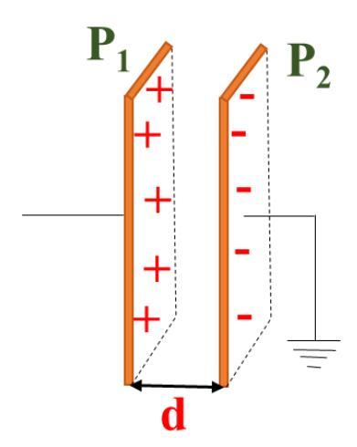
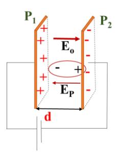
Let us consider two metallic plates P1 and P2 separated by a distance ‘d’ which is small as compared to the dimensions of plates. The plate P1 is given a charge +Q and the plate P2 is earthed as shown in figure above. When charge +Q is given to the plate , the charge -Q is induced on the inner face of plate and charge +Q on its outer face. When the plate is earthed, the charge +Q on its outer face is neutralized due to earthing. The charges +Q and -Q on plates and develop an electric field between them. If each plate has a uniform surface charge density , then electric field E between the plates is uniform and is given by
…(i)
Here is the permittivity of free space (as the plates are kept in vacuum or air).
Also the electric field developed between the plates can be written as
Where V is the electric potential difference between the plates.
From equations (i) and (ii).
Since surface charge density, then above equation becomes,
Since is capacitance (C), so above equation becomes
This is the required expression for capacitance of parallel plate capacitor.
But if the space between the plates is filled with a medium of absolute permittivity ’ ’ then capacitance of the capacitor is given by
Factors affecting the capacitance of parallel plate capacitor:
Section titled “Factors affecting the capacitance of parallel plate capacitor:”The expression for capacitance of parallel plate capacitor is given by
Thus the capacitance of parallel plate capacitor is
- (i) directly proportional to permittivity of medium i.e.
- (ii) directly proportional to area i.e.
- (iii) inversely proportional to permittivity of medium i.e.
Combination of Capacitors:
Section titled “Combination of Capacitors:”In many electric circuits, capacitors are combined suitably to obtain the desired capacitance. There are two basic ways of connecting the capacitors: series combination and parallel combination. When the capacitors are connected in series, the total capacitance decreases while the total capacitance increase when they are connected in parallel.
(i) Series Combinations of Capacitors:
Section titled “(i) Series Combinations of Capacitors:”In the combination, the second plate of the first capacitor is joined to the first plate of the second capacitor and so on. Below figure, shows three capacitors of capacitance , and connected in series.
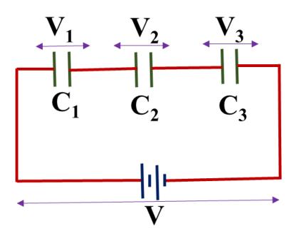
When a battery is connected across the free ends of the series combination, a charge +Q is given to the plate A of the first capacitor it induces a charge -Q on the right face capacitor +Q on the left face of the third capacitor. Similarly two plates of the second capacitor are induced with charge of the same magnitude Q but opposite sign. Therefore, each plate capacitor in this combination contains the same amount of charge as given to the first capacitor.
Let V1, V2 and V3 be the potential difference across C1, C2 and C3 respectively. Then,
The resultant potential difference (V) across the combination is given by
[Since ]
Or,
If Ceq is the equivalent capacities of the series combination, then
From equations (i) and (ii)
Similarly, if there are n capacitors connected in series, then the resultant capacitance, Ceq is given by
Thus, when a number of capacitors are connected in series, the reciprocal of equivalent capacitance is equal to the sum of the reciprocals of the capacitances of each capacitor.
The resultant capacitance in the parallel combination is always less than that of any smallest individual, while the overall potential difference across the combination increases.
(ii) Parallel Combinations of Capacitors:
Section titled “(ii) Parallel Combinations of Capacitors:”The capacitors are said to be connected in parallel if positive plates of all the capacitor are connected together at one point and negative plates are connected together at the other point. In the figure given below three capacitors of capacitance , and are connected in parallel.
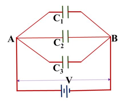
Let the common terminals A and B be connected to a battery having a potential difference V. Let +Q be the charge supplied by the battery to the point A that is distributed among the three capacitors depending upon their capacities. The charge produces same potential across all capacitors. Let , and be the charges distributed on the right side plates of capacitors , and respectively. Then, the total charge supplied
By induction, , and charges will be developed in second plate of capacitors , and respectively. The potential difference across each capacitor is same, V but the charges stores are different as , and . These are given as
Then, Eq. (i) becomes
If Ceq be the resultant capacitance of the parallel combination, then
…(2)
From equations (1) and (2)
Similarly, if there are n capacitors connected in parallel, then the resultant capacitance, C is given by
Thus, when a number of capacitors are connected in parallel, the resultant capacitance is equal to the sum of capacitances of individual capacitor. The capacitance in parallel combination increases while the potential difference for the combination is same as that of individual capacitor. This combination is useful when high
value of capacitance is required at lower potential. In this combination at lower potential, large quantity of charge can be stored.
Energy stored in a charged capacitor:
Section titled “Energy stored in a charged capacitor:”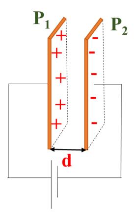
When we connect a battery across the two plates of a capacitor a current flows in the circuit which charges the capacitor. If some charge is developed in the capacitor, an electric field is set up in the capacitor which opposes the charging current of the battery. Therefore, for the battery to charge the capacitor further, work will be done by the battery against the electric field set up in the capacitor. The work done in charging a capacitor is stored in the capacitor in the form of electric potential energy.
Let us consider a capacitor of capacitance C. Suppose that initially the capacitor does not carry charge but after some time it has charge Q and potential V, then
Let the battery supplies a small amount of charge dQ at constant potential difference V, then a small amount of work done by the battery in charging the capacitor is
Or,
Then the total amount of work done in charging the capacitor from 0 to Q is obtained by integrating the above equation as
Or, W =
This work done is stored inside the capacitor in the form of electric potential energy. Thus the energy stored in a capacitor is given by
Substituting Q = C V in equation (i), we get,
…(ii)
Substituting in equation (ii), we get
If Q is in Coulomb, C is in Farad and V is in volt, the energy stored (U) in a capacitor is in Joule. As only half of the supplied energy QV is stored, the remaining part is lost as heat during charging the capacitor by the moving charge.
Uses of Capacitors
Section titled “Uses of Capacitors”There are many applications of the capacitors; some of them are given below.
-
- They can be used as device for storing charge.
-
- Capacitors are used in increasing the efficiency of alternating current power transmission.
-
- The ignition system of any automobile engine contains a capacitor to eliminate the sparking of the points when they open or close.
-
- Capacitors are used in scientific investigation.
-
- To give electric field of desired configuration.
-
- They are also used in oscillators, in filter circuits, in time-delay devices and in many other electronic devices.
Dielectric
Section titled “Dielectric”The material which cannot conduct electric current but can transmit electric field is known as dielectric. Paper, glass, air, pure water, mica etc. are some examples of dielectric.
Effect of Dielectric
Section titled “Effect of Dielectric”Consider a parallel plate capacitor each plate of area A and separated by a distance ‘d’. If the medium between the plates is vacuum or air, the capacitance of capacitor is
…(i)
If the medium of dielectric constant K is placed between two plates of the capacitor the capacitance of capacitor will be
Dividing equation (ii) by (i), we get,
As the dielectric constant K for any medium is greater than that of the vacuum or air, so
Hence, the capacitance increases if a dielectric is placed between the two capacitor plates.
Types of dielectric molecules:
Section titled “Types of dielectric molecules:”There are two types of dielectric; (i) Non polar dielectric molecules (ii) Polar dielectric molecules.
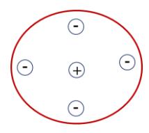
(i) Non polar dielectric molecules:
Section titled “(i) Non polar dielectric molecules:”The molecules in which the centre of gravity of positive charge does not coincide with the centre of gravity of negative charge are known as non-polar molecules.
HCl, H2O, CO, NH3, N2O are some examples of non-polar molecules.
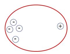
(ii) Polar dielectric molecules:
Section titled “(ii) Polar dielectric molecules:”The molecules in which the centre of gravity of positive charge exactly coincides with the centre of gravity of negative charge are known as non-polar molecules.
O2, H2, N2, CH4, are some examples of polar molecules.
Polarization:
Section titled “Polarization:”When a non-polar dielectric is placed in an electric field, the centre of gravity of positive charge is pulled in the direction of applied electric field while the centre of gravity of negative charges is pulled in the direction opposite to electric field. The process of separation of centre of gravity of positive and negative charges by the application of an electric field is known as polarization.
Due to polarization, an internal electric field is setup but in the direction opposite to applied magnetic field . Due to which resultant electric field decreases and decreases the potential difference between the two plates of capacitor and this ultimately increases the capacitance of the capacitor.
Dielectric Constant (or Relative Permittivity)
Section titled “Dielectric Constant (or Relative Permittivity)”The ratio of capacitance of a capacitor having a dielectric between the plates of the capacitance of the same capacitor without any dielectric (i.e. air or vacuum) is called of the material used. The relative permittivity of substance is denoted by or K and given by
Therefore the relative permittivity or dielectric constant is the ratio of permittivity of medium to that of free space. It has no unit.
Capacitor Numericals
Section titled “Capacitor Numericals”Warm up Numericals:
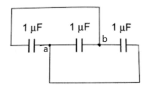
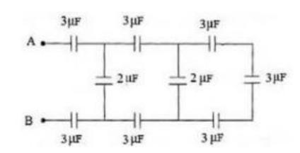
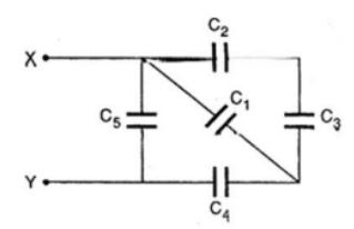
Section titled “Warm up Numericals:”Q. Find the equivalent capacitance of the given figure.
(a)
Ans: 2µF
(b)
Ans: 3µF
(c)
Ans: 1µF
(d)
Given; ; .
Ans:
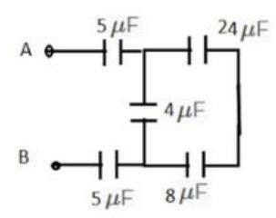
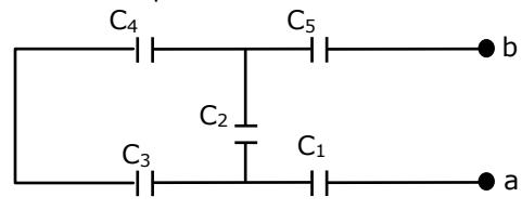
b. In the given capacitors circuit applied potential between a b is 220 V. What is the equivalent capacitance of the network between a and b? Given: . (3)
Ans:?
Numerical Problems
Section titled “Numerical Problems”Q.1 A capacitor is charged from a 20 V d.c. and is found to have carried a charge of 10 C. What was the capacitance of the capacitor and energy stored in it? Ans: C and
Section titled “Q.1 A capacitor is charged from a 20 V d.c. and is found to have carried a charge of 10 μ\muμ C. What was the capacitance of the capacitor and energy stored in it? Ans: 0.5μ0.5\mu0.5μ C and 1×10⁻⁴J1\times10^{-4}J1×10−4J”Here,
Potential
Charge on capacitor,
Capacitance of capacitor,
Energy stored in first capacitor:
We have,
Charge,
And, energy stored,
Q.2 A 300V battery is connected across capacitors of and in parallel. Calculate the energy stored in each capacitors.
Section titled “Q.2 A 300V battery is connected across capacitors of 3μF3\mu F3μF and 6μF6\mu F6μF in parallel. Calculate the energy stored in each capacitors.”Here,
Potential
Capacitance of 1st capacitor (C1) = F = F
Capacitance of capacitor (C2) = F = F
Energy stored in first capacitor:
Energy stored in first capacitor:
Q.3 A parallel plate air capacitor of capacitance 245 pF has a change of magnitude 0.148 C on each plate. Find the potential difference and electric field intensity between the plates if the distance between the plates is 5mm?
Here,
Capacitance of capacity (C) =
Charge on capacitor (q) = 0.418 C = 0.148 C
Distance between plate (d) =
P.d. between plate (V) = ?
Electric field intensity (E) = ?
We have
Or,
Again,
Q. 3 A parallel plate air capacitor has a capacitance of F. What is potential difference is required for a charge of C? What is the total energy stored in it?
Here,
Capacitance (C) = F
Charge (q) = C
Potential Difference (V) = ?
Energy Stored (E) = ?
We know,
Also,
Energy stored,
Q4. Two capacitors of capacitance and respectively are connected in series with a battery of 220V. Find the charge and potential across each capacitor.
Here,
Capacitance of 1st capacitor (C1) =
Capacitance of capacitor (C2) = 12 F = 12×10-6 F
Emf, V = 200 V
We know in series combination of capacitors, charge is same on each capacitor.
Also in series combination of capacitors, potential is divided. i.e.
Or,
And,
Q5. Two capacitors of capacitance and respectively are connected in series with a battery of 200V. Find the charge and potential across each capacitor.
Here,
Capacitance of 1st capacitor (C1) = F = F
Capacitance of capacitor
Emf,
We know in series combination of capacitors, charge is same on each capacitor.
Also in series combination of capacitors, potential is divided. i.e.
Or,
Or,
And,
- Q6. A thundercloud and the earth can be regarded as a parallel plate capacitor. Taking the area of the thundercloud to be 50 km2 and its height above the earth as 1 km and its potential 10 kV, calculate the energy stored. (Permittivity of free space, ) Ans: 2212.5 J
- Q7. What distance should the two plates each of area m2 of an air capacitor be placed in order to have the same capacitance as a spherical conductor of radius 0.5m? Ans: 31.83m
- Q.8 A sheet of paper 40 mm wide and mm thick between metal foil of the same width is used to make a F capacitor. If the dielectric constant of the paper is 2.5, what length of the paper required? Ans: 33.9m
